Observe
Nexa Vision
Visual and geospatial capture of operational areas and infrastructure, clipped per polygon.
Oil and gas infrastructure stretches over hundreds of kilometres and many operational areas are restricted. Convex combines visual perception, recurring territorial monitoring and remote mission coordination to observe those areas without requiring a human presence every cycle.
Oil and gas infrastructure stretches over long distances and includes restricted operational areas. Convex combines visual perception, recurring territorial monitoring and remote mission coordination to observe those areas without requiring a human presence every cycle.
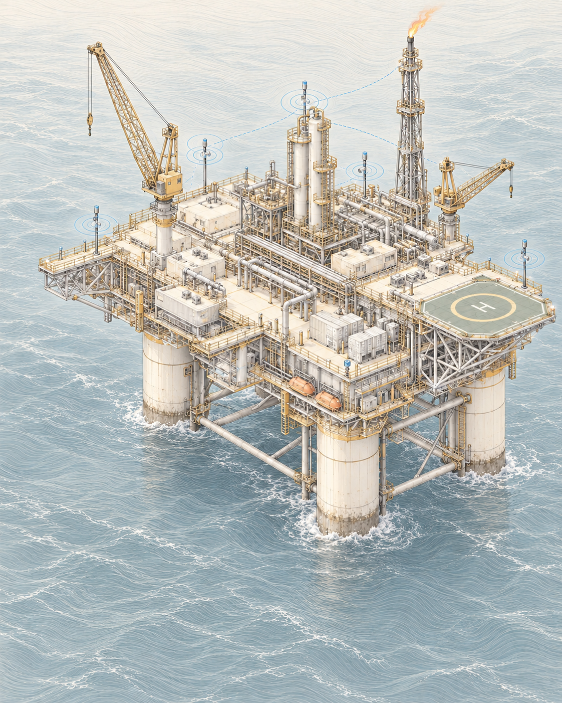
Pipelines, well pads, tanks and processing units stretch over hundreds of kilometres, making frequent on-site inspection unfeasible.
Hazardous locations need inspection, yet every visit is an exposure that has to be justified.
Operational areas shift between cycles; without temporal comparison the change goes unnoticed.
Photos and walkthroughs exist, but seldom form a comparable history of the same area.
Weather and lighting conditions affect perception and must be handled in processing.
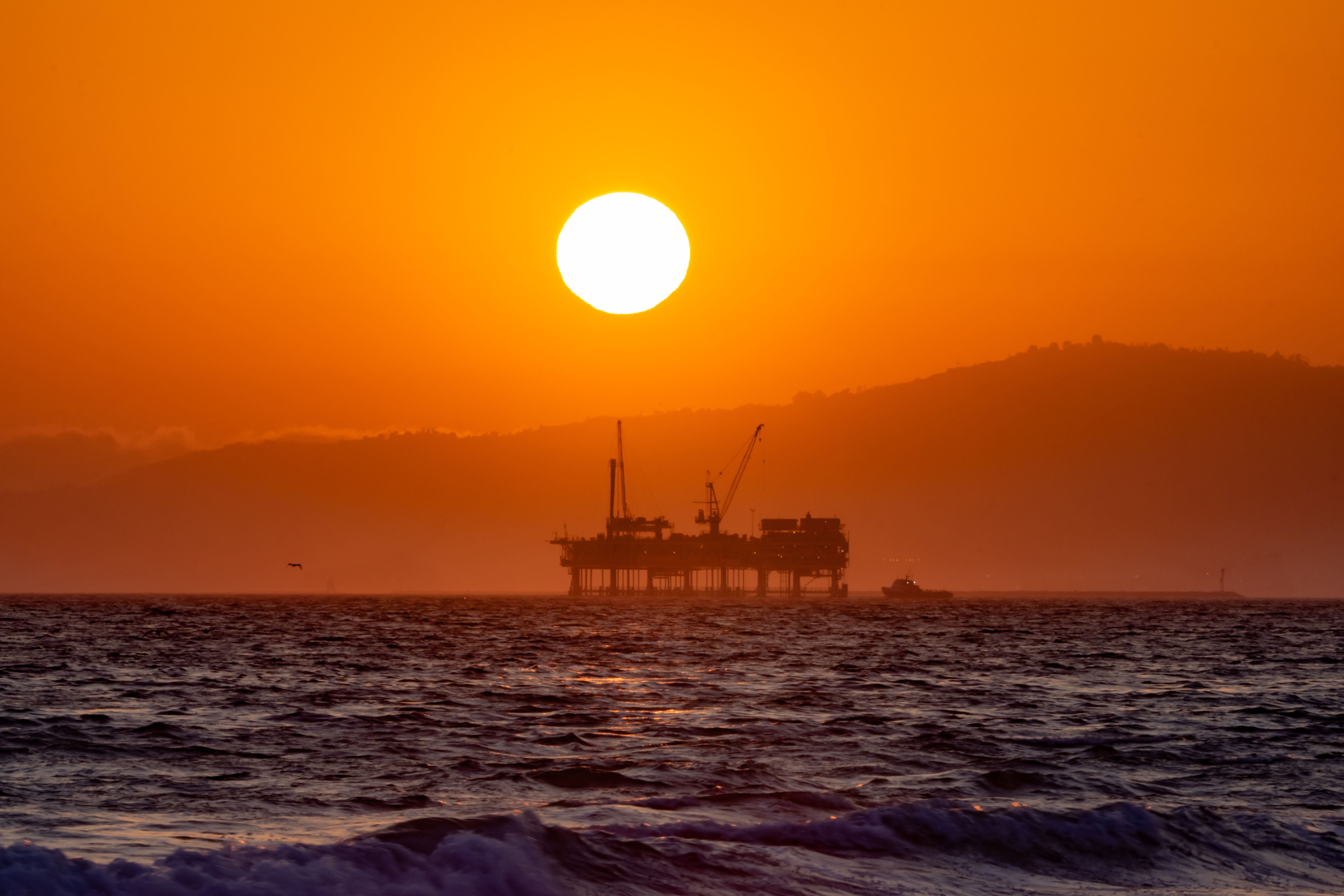
/ Intelligence and computer vision in oil and gas
From operational observation to diagnosis, turning data into clearer operational decisions.
The same architecture runs across every sector. What changes is which layer is critical and which proprietary systems take part.
Visual and geospatial capture of operational areas and infrastructure, clipped per polygon.
Reading of change between cycles and a written diagnosis of the observed area.
Environmental context for the period: rainfall, temperature and conditions affecting the area.
Planning and state of remote inspection missions, with telemetry.
Physical execution in the operational area, where technically applicable. In development.
Sources compatible with the systems deployed in this sector. No layer is assumed: every monitored area declares what is actually available.
Visual captures of infrastructure and inspected areas.
Polygons of operational areas and clipping per region of interest.
Comparison of the same area across successive cycles.
State of the platforms carrying out the inspection mission.
Planned route, execution and result of each cycle.
Local weather conditions during the observed interval.
Each application states the problem addressed, the data used, the Convex system involved and the operational output produced.
On-site inspection is expensive and exposes personnel to risk.
Gradual alterations go unnoticed without temporal comparison.
Extent exceeds the capacity of on-site inspection.
Need to repeat the same route consistently.
Weather conditions explain part of what the image shows.
The inspection mission covers the area and records the visual material for the cycle.
Captures are clipped per region of interest and normalised.
Nexa M1 compares the cycle with the history and describes the observed changes.
Regions with relevant change are highlighted for technical assessment.
The team decides on a targeted inspection or intervention on the flagged point.
The cycle is archived and becomes the reference for the next comparison.
Spatial clipping of observed areas and infrastructure.
Highlight of relevant changes between cycles.
Evolution of the same area over time.
State of the platforms during the mission.
Consolidation per cycle and per monitored area.
Comparable and queryable visual record.
We separate what is in operation from what is still under development. Research and prototypes are never presented as deployed product.
Capture, clipping and comparable record across cycles. Potential application under study.
Recurring observation with geospatial clipping and per-cycle report. Potential application under study.
Comparative reading across cycles of the same area. Potential application under study.
Planning and coordinated execution of recurring routes.
Robotic actuation in the operational area, where technically applicable.
Linear stretches requiring recurring coverage.
Operational regions with frequent configuration changes.
Areas that change in volume and geometry between cycles.
Distributed facilities requiring periodic verification.